Figuring out how to model a little wriggler as in the sketch below, I encountered a few problems. I think I understand better now. Let me tell you about it.
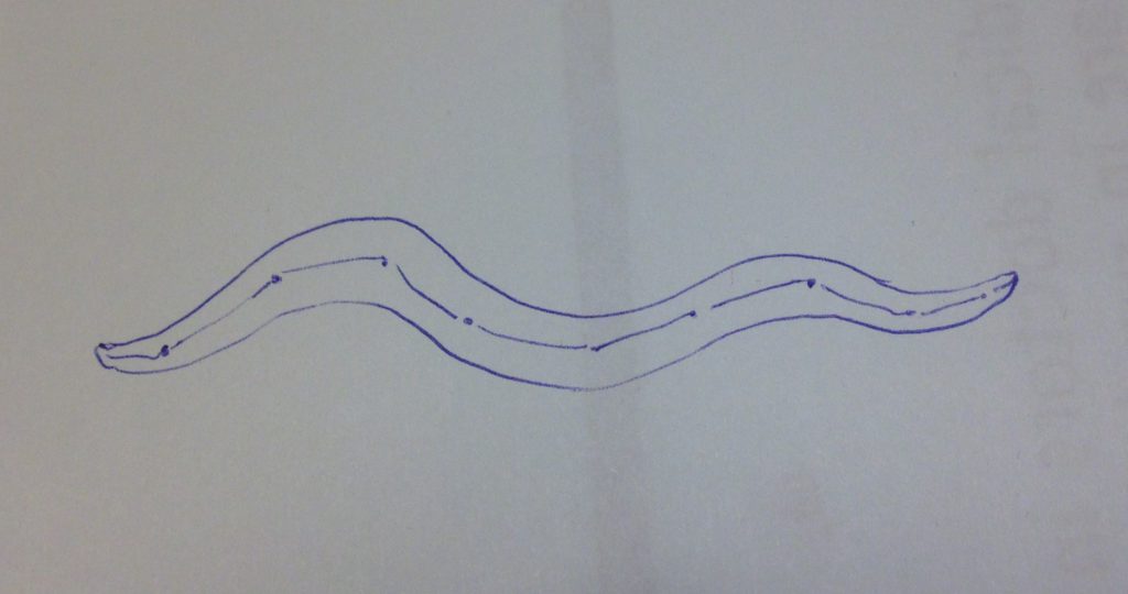
Primitive form of a worm
Create a cylindrical shape that is going to play the role of worm in this story. Rotate the object to have the creature in horizontal position.

Worm with a backbone
Add an armature. Make the first bone bigger by enlarging the radius, if you want. But do not scale the bone afterwards while still in Object Mode, transforming the armature. Scaling in Object Mode will cause errors and confusion, just like it does when working with modeling tools.
In Edit Mode create a chain of bones by repeatedly extruding the previous bone.
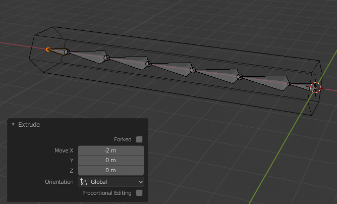
It’s just a simple skeleton for a simple creature. It just needs to wriggle a little.
Follow the bone
Back in Object Mode select the cylinder, then the armature. Choose Parent > Armature Deform > With Automatic Weights (in Object menu, context menu or press Ctrl-P).
Will it pose?
In Pose Mode rotate a few bones, to see what happens.
It’s clear our object doesn’t deform well. It lacks vertices. Maybe a little subdivision (with Subdivision Modifier would help?)
Ehm, no. Of course the subdivision is applied after the deformation by the armature. Maybe if we swapped the Armature and Subdivision modifiers. (Aha, setting the armature as parent to the worm did actually add a modifier to the worm.)

It’s bend a bit, but still no good. Let’s go back a few steps and add some vertices ourselves.
Add worm segments
To edit the worm (add loop cuts), first clear the parent relationship between cylinder and armature (Alt-P) and reset the armature. (In Pose Mode, select all, press Alt-R). Adding loop cuts while the worm is still deformed by the armature raises a warning, and may possibly results in problems lateron.
Maybe it’s wise to remove the vertex groups (Bone, Bone.001, etc.) of the cylinder too. They were added when the armature was chosen as parent, but stayed behind when the parenthood ended.
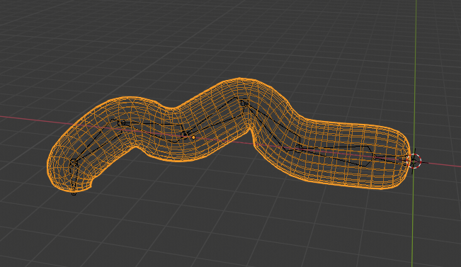
Now that’s been cleared up, add a number of loop cuts, to divide the worm in segments. About one segment per bone makes sense.
Set the parent-child relation again, and pose the armature.
Order of modifiers
There is progress, but in places where the bones are bend quite sharply, it almost seems there are too many points now and the armature doesn’t know where to put them.
Well, now the parent relationship is set up again, the Armature Modifier is added after the Subdivision Modifier that was still active. Better let the bones deform the basic shape, then smooth things out with subdivision.

Definitely better. Getting warm. Let’s just make it look a little more like the first sketch.
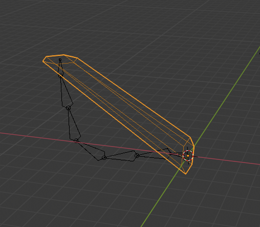
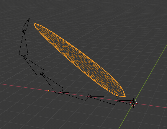
Getting thin
In Edit Mode, scale down the cylinder a bit in the YZ-plane (in this case). Scale down the nose and tail face a bit extra to taper the ends.
Fortunately, these edits can be done without breaking the parentship again.

Conclusion
- Keep your model simple, but not too simple.
- Beware of the order that modifiers apply.
- Edit in Edit Mode, not Object Mode.